The exploded diagram of the worm gear box assembly. The parts are as

Download scientific diagram | The exploded diagram of the worm gear box assembly. The parts are as follows: 1-cover; 2-bearing; 3-worm shaft; 4-cover; 5-bearing; 6-gear box body; 7-bearing; 8-oil seal; 9-cover; 10-plug; 11-worm gear rim; 12-worm gear hub; 13-output shaft; 14-bearing; 15-oil seal; 16-cover from publication: Image-assisted collision detection for calculation of an assembly interference matrix | The assembly interference matrix is a foundational information model for assembly process planning such as assembly sequence and assembly path planning, and supports digital assembly simulation, intelligent assembly, digital twin-based assembly, and so on. The assembly | Collision Detection, Assembly and Matrix | ResearchGate, the professional network for scientists.

Exploded Diagram Stock Illustrations – 189 Exploded Diagram Stock Illustrations, Vectors & Clipart - Dreamstime
MTD 31AH5DV8897 CA328 (2018) Parts Diagram for Auger Gearbox Assembly
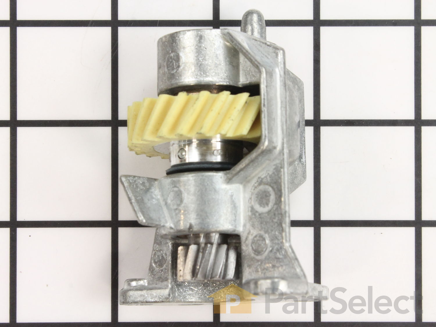
Worm Gear and Bracket WP240309-2, Official Whirlpool Part, Fast Shipping
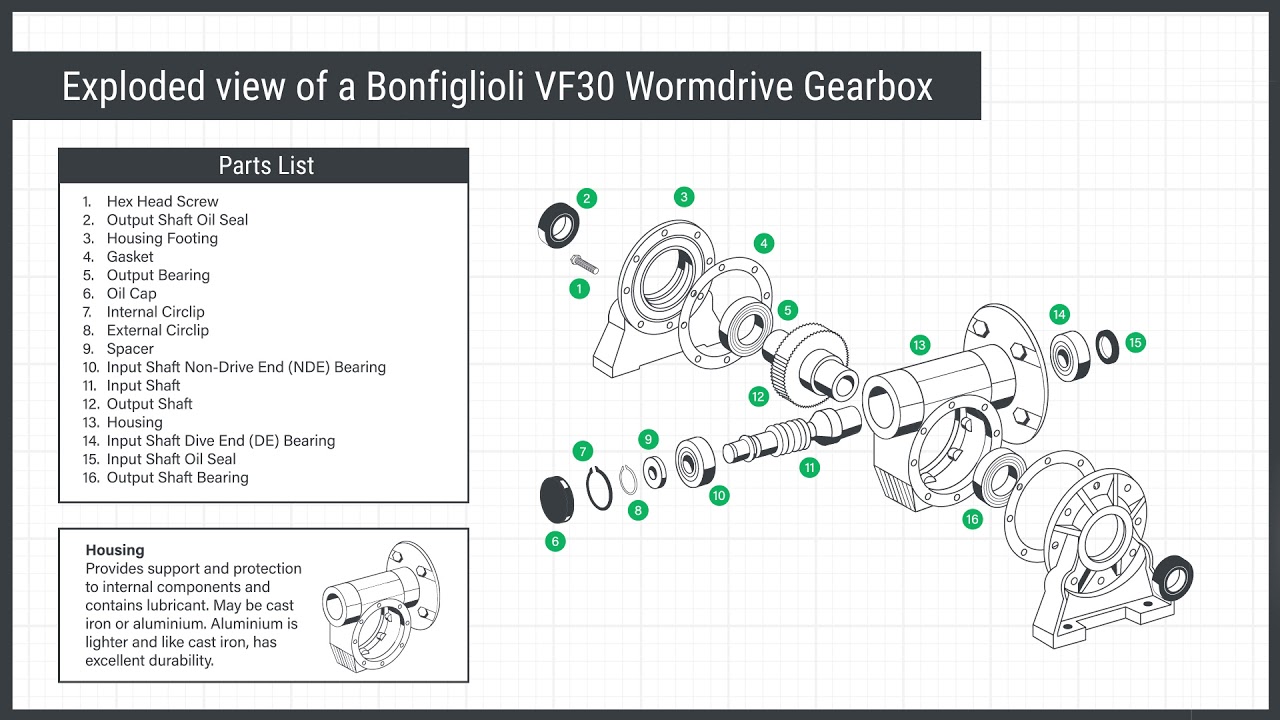
Wormdrive gearbox animation: exploded view

HydroWORKS 8607400 Aluminum Worm Gear Speed Reducer Instruction Manual
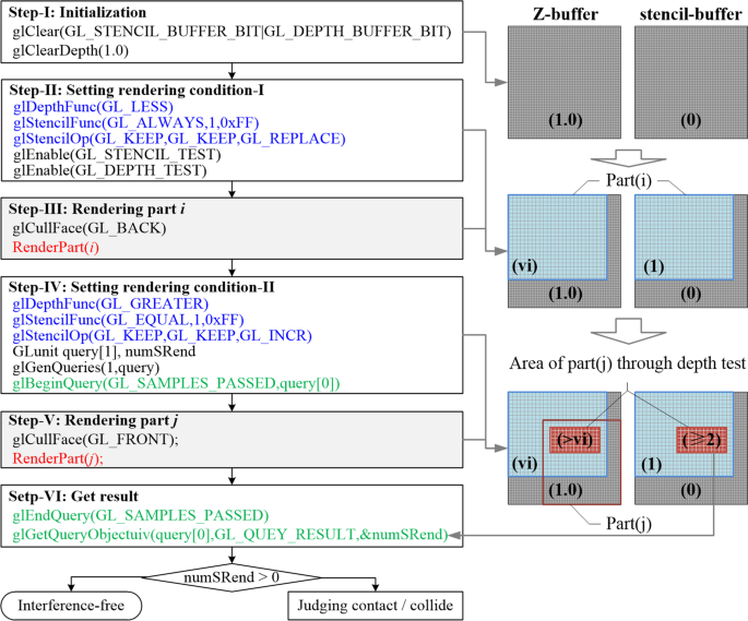
Image-assisted collision detection for calculation of an assembly interference matrix

The exploded diagram of the worm gear box assembly. The parts are as
Echo ST-5024 Type 1 Parts Diagram for Impeller Assembly, Worm Gear, Auger Shaft, Gear Case
Troy Bilt 31AM6BP2766 Storm 2420 (2016) Parts Diagram for Chute Gearbox

The exploded diagram of the worm gear box assembly. The parts are as

AUMA Part-Turn Gearbox Spare Parts – ProActuator
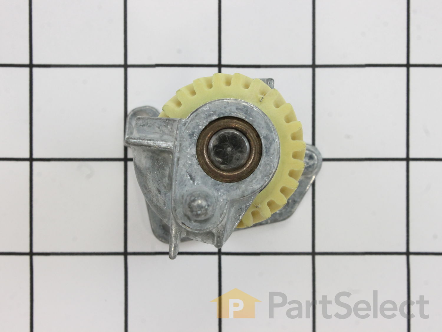
Worm Gear and Bracket WP240309-2, Official Whirlpool Part, Fast Shipping
Competitive price worm gearbox has 50mm center distance, 27 Nm rated torque, 1400 rpm rated speed. The reduction ratio can be customized to 5:1/
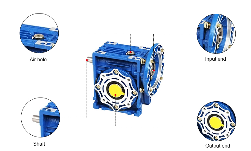
50mm Worm Gearbox, Ratio 5:1 to 100:1, 27 N.m